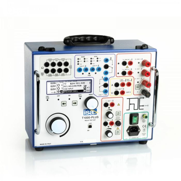
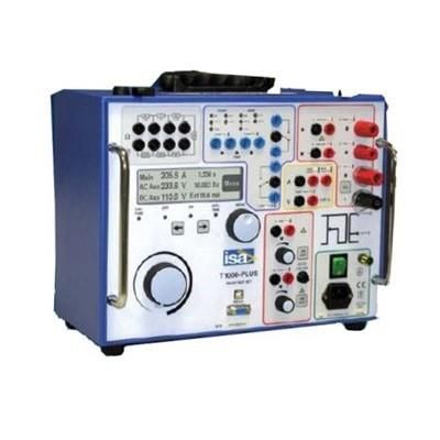
T-1000 PLUS Device for testing relay protection devices in single-phase mode - I.S.A. - Altanova group
The T-1000 PLUS device is designed for testing various types of relay protection devices and other primary and secondary equipment in single-phase mode. It combines high power, small dimensions and weight and is a reliable assistant in the setup and operation of protections.The device for testing relay protection and automation T-1000 PLUS manufactured by ISA (Italy) is designed to test all types of relay protection in single-phase mode, as well as other primary and secondary equipment.
The device has three generators with built-in measurement circuits:
- main (AC 0-250 A, AC voltage 0-250V/500 V, DC 300 V)
- auxiliary AC voltage (DC voltage 300 V) with frequency and phase angle adjustment
- auxiliary DC voltage (20-240 V) for powering protection
The built-in module for measuring external quantities allows you to measure external currents and voltages, frequency and phase angle and calculate other indirect parameters based on them.
A distinctive feature is the large LCD display and built-in controls. Test results can be saved to the internal memory of the device and transferred to a PC for generating a protocol. T-1000 PLUS can be connected to a PC using a special TDMS software package. Software in Russian is included in the standard delivery package of the T-1000 PLUS and allows you to create reports.
In addition to the T-1000 PLUS device, the following modules can be supplied:
- D-1000 (conversion of an auxiliary AC voltage source into a second current source) for testing differential relay protection, with a current of 5A,
- current filter FT-1000 for filtering interference from the device’s power supply network,
- SHA 1000 reading head for checking electricity meters.
The T-1000 PLUS relay protection tester weighs only 19 kg and comes in a shock-resistant plastic case.
Functional features of T1000 Plus:
- Maximum output current 250 A
- Max. output alternating voltage up to 260V/500V (AC)
- Max. DC output voltage 300 V (DC)
- Frequency generator 15 - 550 Hz
- Smooth phase shift
- Protection power supply 20-240 V DC
- Oscilloscope function for current and voltage
- Data transfer via USB port
- Saving results to internal memory
- Free software in Russian
- Large graphic display
- Compact and lightweight
- Initial verification of the device is included in the price
Models | Main exits | Additional outputs | |||
Imax | Umax AC | Umax DC | Umax AC | Umax DC | |
TD-1000Plus | 250 A | 250 V | 300 V | 260 V | 240 V |
T-1000-E Plus | 250 A | 500 V | 300 V | 500 V | 240 V |
Main generator
Alternating current
Maximum output power, VA | 1000 |
Rated output reduced power, VA | 60 |
Maximum output alternating current, A | 250 |
Maximum output alternating current in reduced power mode, A | 70 |
Main permissible relative error, % | 1.0 |
AC voltage
Maximum output power, VA | 750 |
Maximum output voltage, V | 250 or 500 |
Rated output current, A | 2 |
Main permissible relative error, % | 1.0 |
Constant pressure
Maximum output power, VA | 500 |
Rated output reduced power, VA | 60 |
Maximum output voltage, V | 300 (straightened smoothed) |
Main permissible relative error, % | 0.5 |
Auxiliary alternating voltage generator
AC voltage
Rated output power, VA | thirty |
Maximum output power (1 min), VA | 40 |
Maximum output voltage, V | 260 |
Output current, A | 0.5; 0.25; 0.125 |
Phase angle adjustment range, ° | 0 – 360 |
Angle resolution, ° | 1 |
Possibility of setting pre-failure voltage | There is |
Possibility of setting the angle of pre-emergency voltage relative to emergency voltage | There is |
Ability to set the duration of the pre-emergency mode | There is |
Frequency control range, Hz | 15 – 550 |
Frequency control step, Hz | 0.001 |
Possibility of switching from rated frequency to emergency frequency | There is |
Setting range for frequency change rate, Hz/s | 0.01 – 99.99 |
Main permissible relative error, % | 1.0 |
Auxiliary DC voltage generator (power supply for the protection being tested)
Rated output power, W | 90 |
Maximum output voltage, V | 240 |
Maximum output current, A | 0.9; 0.45 |
Main permissible relative error, % | 0.5 |
Measuring inputs
Type of current | DC/AC |
Voltage measurement limits, V | 19.99; 59.99; 199.9; 599.9 |
Current measurement limits, A | 0.025(constant); 1.999; 10.49 |
Basic add. relates measurement error fast. voltage, % | 0.5 |
Basic add. relates measurement error AC voltage, % | 1.0 |
Basic add. relates current measurement error, % | 0.5 for range 0.025A and 1.0 |
Built-in digital stopwatch
Measurement limits, s | 9.999; 99.99; 999.9; 9999 |
Limits of permissible absolute error of time measurement (in accordance with measurement limits), ms | ±(0.005%+ 1 unit ml.r) |
Type of digital inputs | “dry”, with a potential of 250V(AC) or 275V(DC) |
Reaction to contact inversion | yes (one of the presets) |
Ability to set NO or NC contact status | There is |
Ability to set a threshold value for a discrete input | 24V, 48V, 110V |
Mode for counting the number of pulses received at a discrete input (checking electricity meters) | yes, with a frequency of 10 kHz |
Auxiliary contact outputs
Number of contact outputs, pcs. | 2 |
Maximum time delay, s | 999.9 |
Limits of permissible absolute time delay error, ms | 1 |
Switching capacity of contacts | 5A, 250V |
General information
Number of generators | 3 |
Ability to start/stop generators | There is |
Source 2 Reduced Power Mode (Main Generator*) | There is |
Number of ballast resistors | 6 |
Nominal values of ballast resistors, Ohm | 0.5; 1; 22; 470; 1000; 2200 |
Presence of ballast resistor sockets on the front panel | There is |
Custom Ballast Resistor Setting | There is |
Number of digital inputs | 2 |
Ability to set a threshold value. discrete entrance | There is |
Number of contact outputs | 2 |
Number of voltage measuring inputs | 1 |
Number of current measuring inputs | 2 |
Internal memory for test conditions and results | There is |
Synchronization of devices with each other to obtain a three-phase system of currents and voltages | There is |
PC communication interface | RS-232, USB |
External software for analyzing and printing results | There is |
Additional measurements on generator outputs | P, Q, S, cos ?, Z, ?, R, X |
Additional measurements on measuring inputs | P, Q, S, cos ?, Z, ?, R, X, f, W |
Module for checking diff. protection (separate block) | There is |
Output current filter (separate unit) | There is |
Possibility of testing in reclosure cycles | There is |
LCD display | There is |
Power supply, V | 230 ± 15% |
Operating temperature range, °C | 0 to +50 |
Weight, kg | 19 |
Overall dimensions, mm | 380x300x240 |
- Device T -1000 PLUS
- Standard Test Cable Set
- Power cable
- USB cable
- Spare fuses (No. 5), T5A.
- TDMS software.
- Plastic case
- Manual
- Warranty card "GK Energoscan"
- Certificate of initial verification
Additional equipment
- Additional cable set
- Differential protection testing module D-1000 / D-2000
- Current filter FT-1000
- Converter to low signal
Guarantee period 1 год


