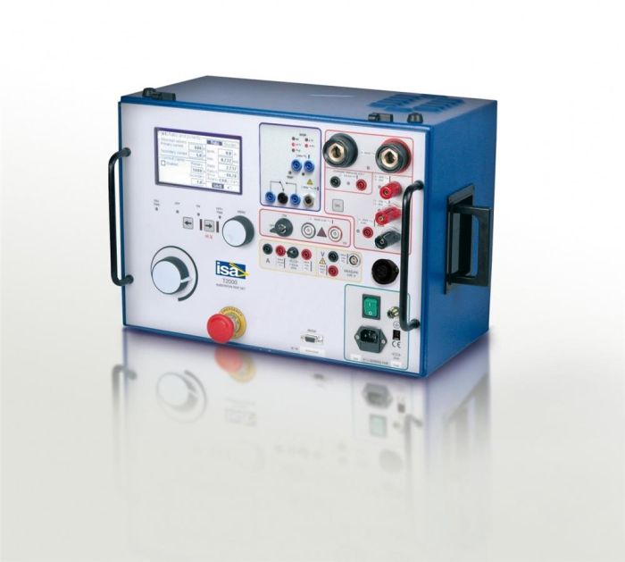
T-2000 Current and voltage transformer testing device - I.S.A. - Altanova group
Multifunctional system for testing current transformers (CT), voltage transformers (VT), power transformers, overcurrent protection, electricity meters, converters and grounding networks. The T-2000 allows for semi-automatic testing, which significantly reduces test time and prevents errors.The T-2000 device is designed for testing current transformers (CT), voltage transformers (VT), power transformers, overcurrent protection, electricity meters, converters and grounding networks.
The T-2000 test system includes one main generator with 6 outputs: high-current AC (up to 800 A), low-current AC (up to 60 A), low-current DC (up to 6 A), pulse current (up to 10 A) , high-voltage alternating voltage (up to 3000 V), low-voltage alternating voltage (250 V). All outputs are adjustable and have their own meters.
Parameter checks are carried out in semi-automatic mode. The operator selects the type of test, the outputs used and controls the output values. The device, in turn, measures output and input quantities and calculates indirect parameters, such as transformation ratio, resistance, inflection point when taking the current-voltage characteristic
The current status of the output values is displayed on the large graphic LCD display. Using the multifunction control button and the graphic LCD display, you can enter the MENU mode, with which you can control all functions of the device.
Test results can be recorded, viewed and analyzed using TDMS software. The TDMS program is available entirely in Russian, it allows you to control the T-2000 setup, download test results, prepare professional test reports and export them to various formats using a graphical user interface.
In addition to the T-2000 device, various options can be supplied that expand the functionality of the device.
MEASURED PARAMETERS T-2000
| Current transformers (CT) |
|
| Voltage transformers (VT) |
|
| Power transformers (PT) |
|
| Grounding devices (GD) |
|
The main purpose | TT, TN, ST |
PC connection | RS-232 |
Graphic display | LCD display FSTN; black and white, 240x128 pixels; size - 135x80 mm |
Local memory for storing results | 500 results |
External software for loading test conditions and analyzing results | TDMS |
Number of generators, pcs. | 3 |
Number of discrete inputs, pcs. | 2 |
Number of contact outputs, pcs. | 1 |
Ability to set the sensitivity threshold of discrete inputs | There is |
Possibility of synchronizing devices to obtain a three-phase system | There is |
Possibility of testing in reclosure cycles | There is |
Nominal values of ballast resistors, Ohm | 1000; 2200 |
Main generator
High Current AC Output
Maximum output current, A | 800 |
Rated output power, VA | 600 |
Maximum output power, VA | 2000 |
Low current AC output
Maximum output current, A | 60 |
Maximum output power, VA | 1000 |
Low current DC output
| Maximum output current, A | 6 |
Maximum current in current pulse mode, A | 10 |
High voltage AC output
Maximum output voltage, V | 1200 or 3000 |
Maximum power, VA | 1500 |
Low voltage AC output
Maximum output voltage, V | 250 |
Maximum output power, VA | 250 |
Meter
Main relative error of alternating voltage measurement, % | 0.5 |
Main relative error of DC voltage measurement, % | 0.5 |
Main relative error of current measurement, % | 0.5 |
Absolute error of phase angle measurement, degrees. | 1 ±1 unit ml.size |
Absolute frequency measurement error, mHz: - at a frequency of 50 Hz - at the upper limit of the frequency range | 1 10 |
Possibility of calculating derived values from generator outputs (cos ?, Z, R, X, P, Q…) | There is |
Possibility of calculating derived values from measuring inputs (cos ?, Z, R, X, P, Q…) | There is |
Possibility of indication in I/Inom, U/Unom | There is |
Stopwatch
Absolute error of time measurement, ms: - from 0 to 9.999s - from 10 to 99.99s - from 100 to 999.9s - from 1000 to 9999s | 1 10 100 1000 |
Possibility of time indication in power frequency periods | There is |
Other parameters
Operating temperature range, °C | -10 to +50 |
Power supply voltage (1 phase, 50 Hz), V | 220±15% |
Weight | 34 |
- Device T-2000
- Set of test cables;
- Power cable;
- Grounding cable;
- RS232 cables
- Manual
- Warranty card of Energoscan Group of Companies
- Certificate of initial verification
Additional equipment:
- Aluminum transport case
- Discovery's heavy-duty transport case (plastic)
- Clamp meter 1/1000, max. 100A - ? 12 mm
- External 4.5" thermographic printer
- External DC module High I DC 400 A
- Scanning head SH-2003 for checking meters
- Upgraded load current transformer up to 2000A
- Upgraded load current transformer up to 3000A
- Upgraded load current transformer up to 4000A
- Kit for measuring the resistance of grounding devices and determining soil resistivity
- Current filter FT-1000
- Safety module for line impedance measurement
Guarantee period 1 год


