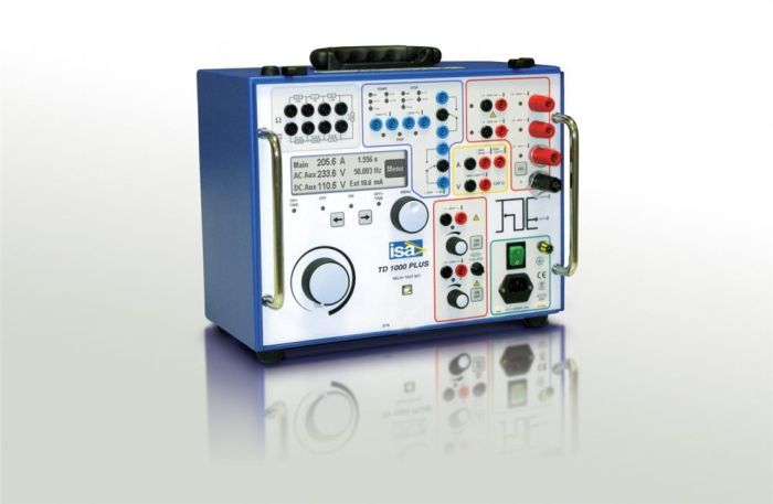
TD-1000 PLUS Device for testing relay protection devices in single-phase mode - I.S.A. - Altanova group
The TD-1000 device is designed to test various types of relay protection devices and other primary and secondary equipment in single-phase mode. Combines high power, small dimensions and weight. This is an indispensable and reliable assistant when setting up and operating protections. It differs from the T-1000 Plus device in the ability to generate a second current source for testing differential protection.The device for testing relay protection and automation TD-1000 PLUS is designed to test all types of relay protection in single-phase mode, as well as other primary and secondary equipment.
The device has three generators with built-in measurement circuits:
- main (AC 0-250 A, AC voltage 0-250 V, DC 300 V)
- auxiliary AC voltage (0-260V) with adjustable frequency and phase angle / auxiliary AC source (0-20A)
- auxiliary direct voltage (20-240V) for powering protection
What distinguishes this model from the T-1000 Plus model is the ability to automatically convert the auxiliary alternating voltage generator into a second current source for testing differential protection.
The built-in module for measuring external quantities allows you to measure external currents and voltages, frequency and phase angle and calculate other indirect parameters based on them.
Test results can be saved to the internal memory of the device and transferred to a PC for generating a protocol. The device can also be connected to a PC using a special TDMS software package. Software in Russian is included in the standard delivery kit of the device and allows you to create reports.
Additional to the device TD -1000 Plus modules can be supplied:
- current filter FT -1000 for filtering interference from the device power supply
- reading head SHA 1000 for checking electricity meters
The TD-1000 PLUS relay protection tester weighs only 19 kg and comes in a shock-resistant plastic case.
Functional features of TD1000 Plus:
- Maximum output current 250 A
- Max. output alternating voltage up to 260 V (AC)
- Max. DC output voltage 300 V (DC)
- Second current source for testing differential protection
- Frequency generator 15 - 550 Hz
- Smooth phase shift
- Protection power supply 20-240 V DC
- Oscilloscope function for current and voltage
- Data transfer via USB port
- Saving results to internal memory
- Free software in Russian
- Large graphic display
- Compact and lightweight
- Initial verification of the device is included in the price
Models | Main exits | Additional outputs | ||||
Imax | Umax AC | Umax DC | Umax AC | Umax DC | Imax | |
T D- 1000 Plus | 250 A | 250 V | 300 V | 260 V | 240 V | 20A |
T D- 1000 Plus 15 Hz | 250 A | 250 V | 300 V | 260 V | 240 V | 20A |
Main generator
Alternating current
Maximum output power, VA | 1000 |
Rated output reduced power, VA | 60 |
Maximum output alternating current, A | 250 |
Maximum output alternating current in reduced power mode, A | 70 |
Main permissible relative error, % | 1.0 |
AC voltage
Maximum output power, VA | 750 |
Maximum output voltage, V | 250 |
Rated output current, A | 2 |
Main permissible relative error, % | 1.0 |
Constant pressure
Maximum output power, VA | 500 |
Rated output reduced power, VA | 60 |
Maximum output voltage, V | 300 (straightened smoothed) |
Main permissible relative error, % | 0.5 |
Auxiliary alternating voltage generator
AC voltage
Rated output power, VA | thirty |
Maximum output power (1 min), VA | 40 |
Maximum output voltage, V | 260 |
Output current, A | 0.5; 0.25; 0.125 |
Output current in current output mode, A | 20 A |
Phase angle adjustment range, ° | 0 – 360 |
Angle resolution, ° | 1 |
Possibility of setting pre-failure voltage | There is |
Possibility of setting the angle of pre-emergency voltage relative to emergency voltage | There is |
Ability to set the duration of the pre-emergency mode | There is |
Frequency control range, Hz | 15 – 550 |
Frequency control step, Hz | 0.001 |
Possibility of switching from rated frequency to emergency frequency | There is |
Setting range for frequency change rate, Hz/s | 0.01 – 99.99 |
Main permissible relative error, % | 1.0 |
Auxiliary DC voltage generator (power supply for the protection being tested)
Rated output power, W | 90 |
Maximum output voltage, V | 240 |
Maximum output current, A | 0.9; 0.45 |
Main permissible relative error, % | 0.5 |
Measuring inputs
Type of current | DC/AC |
Voltage measurement limits, V | 19.99; 59.99; 199.9; 599.9 |
Current measurement limits, A | 0.025(constant); 1.999; 10.49 |
Basic add. relates measurement error fast. voltage, % | 0.5 |
Basic add. relates measurement error AC voltage, % | 1.0 |
Basic add. relates current measurement error, % | 0.5 for range 0.025A and 1.0 |
Built-in digital stopwatch
Measurement limits, s | 9.999; 99.99; 999.9; 9999 |
Limits of permissible absolute error of time measurement (in accordance with measurement limits), ms | ±(0.005%+ 1 unit ml.r) |
Type of digital inputs | “dry”, with a potential of 250V(AC) or 275V(DC) |
Reaction to contact inversion | yes (one of the presets) |
Ability to set NO or NC contact status | There is |
Ability to set a threshold value for a discrete input | 24V, 48V 110V |
Mode for counting the number of pulses received at a discrete input (checking electricity meters) | yes, with a frequency of 10 kHz |
Auxiliary contact outputs
Number of contact outputs, pcs. | 2 |
Maximum time delay, s | 999.9 |
Limits of permissible absolute time delay error, ms | 1 |
Switching capacity of contacts | 5A, 250V |
General information
Number of generators | 3 |
Ability to start/stop generators | There is |
Source 2 Reduced Power Mode (Main Generator*) | There is |
Number of ballast resistors | 6 |
Nominal values of ballast resistors, Ohm | 0.5; 1; 22; 470; 1000; 2200 |
Presence of ballast resistor sockets on the front panel | There is |
Custom Ballast Resistor Setting | There is |
Number of digital inputs | 2 |
Ability to set a threshold value. discrete entrance | There is |
Number of contact outputs | 2 |
Number of voltage measuring inputs | 1 |
Number of current measuring inputs | 2 |
Internal memory for test conditions and results | There is |
Synchronization of devices with each other to obtain a three-phase system of currents and voltages | There is |
PC communication interface | RS-232, USB |
External software for analyzing and printing results | There is |
Additional measurements on generator outputs | P, Q, S, cos ?, Z, ?, R, X |
Additional measurements on measuring inputs | P, Q, S, cos ?, Z, ?, R, X, f, W |
Module for checking diff. protection (separate block) | There is |
Output current filter (separate unit) | There is |
Possibility of testing in reclosure cycles | There is |
LCD display | There is |
Power supply, V | 230 ± 15% |
Operating temperature range, °C | 0 to +50 |
Weight, kg | 19 |
Overall dimensions, mm | 380x300x240 |
- Device TD-1000 PLUS
- Standard Test Cable Set
- Power cable
- USB cable
- Spare fuses (No. 5), T5A.
- TDMS software.
- Plastic case
- Manual
- Warranty card "GK Energoscan"
- Certificate of initial verification
Additional equipment TD-1000 Plus
- Cable kit (optional)
- Current filter FT-1000
- read head SHA 1000
Guarantee period 1 год


